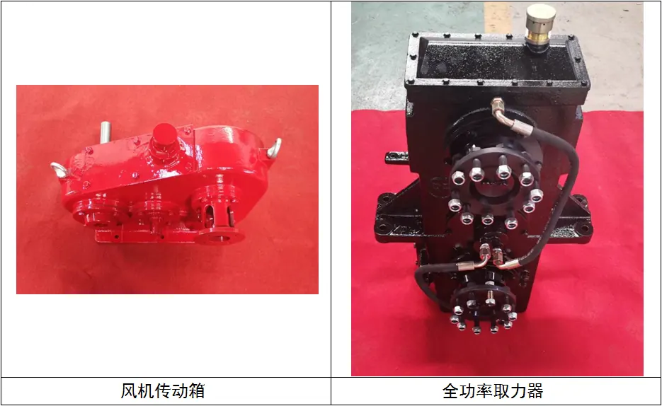
Identify each shaft and its mating component
Label the input, output and auxiliary connections on the arrangement drawing. State whether the supplier provides a bare shaft, hub, complete coupling or another mating assembly. A reference to standard shaft ends does not define what the purchaser receives. Identify the connection used by the actual prime mover and driven equipment, including adapters already installed. Keep each power path associated with the required duty and rotation reference.
Define the geometry without relying on appearance
Request the relevant shaft, key, spline or flange details in a controlled interface specification. Include the agreed reference system, dimensions, tolerances and applicable definition where established by the mating-component designer. Similar-looking splines or bolt patterns are not proof of interchangeability. If information is incomplete, have the supplier identify the measurements or records required before confirming the connection. Do not convert a field photograph into an unqualified manufacturing instruction.
Review retention and assembly boundaries
Ask which retaining components, fasteners, fit requirements and installation documents accompany the offered connection. The responsible designers should define the assembly and service requirements for the selected shaft system. Compare a supplied coupling assembly with an offer that leaves hubs or retention hardware to the purchaser. Those alternatives can have different installation, inspection and spare-parts implications even when their commercial descriptions use the same input or output shaft terminology.
Connect coupling selection with actual duty
Provide the relevant torque, speed, displacement and environmental cases to the component and drive-train designers. A coupling must be reviewed for its task within the system, not selected only because its bore fits. Ask how the proposed component affects alignment, reaction loads and any torsional assessment. Identify the supporting calculations or supplier documents required by the project and keep the selected coupling associated with the gearbox configuration being purchased.
Include evidence for the delivered interfaces
Agree the dimensional records and component identification needed at acceptance. Where a trial fit or mating-part check is proposed, state what it demonstrates and which supplied items it covers. Retain the final connection drawings and part identifiers with the handover package. This allows the operator to distinguish a compatible replacement from a visually similar component and reduces dependence on informal descriptions when couplings or shaft hardware are ordered later.
Avoid splitting responsibility at an undefined hub
If the gearbox vendor supplies only one side of a connection, identify who selects and verifies the complete mating arrangement. Include coupling guards, assembly access and any required specialized tools in the installation scope where applicable. The commercial comparison should not count a partially supplied shaft connection as equivalent to a complete drive interface. Clear ownership is particularly important for replacements where the existing coupling condition or previous modification may affect the feasibility of reusing it.
Put these items side by side in the bid review
| Purchase item | Question to resolve | Evidence to request |
|---|---|---|
| Geometry | What exact shaft-end definition applies? | Controlled interface details |
| Supply boundary | Bare shaft, hub or full assembly? | Priced component schedule |
| Verification | How is mating compatibility established? | Agreed dimensional or fit evidence |
Suggested wording for the quotation request
List the supplied shaft ends, splines, keys, flanges, hubs and couplings by interface. Identify geometry definitions, mating-part information, retention hardware and assembly documents. State excluded components and the dimensional or trial-fit evidence proposed for acceptance.
Assess each option within the complete gearbox drive train: prime mover, transmission, couplings, driven equipment, mounting and supporting oil system. Preserve the accepted load schedule and interface drawings when comparing suppliers or approving changes. A component rating should not be treated as proof of the complete installed arrangement. Obtain configuration-specific documents from the responsible designers, and retain the agreed exclusions and verification records with the equipment order. Installation, shifting, testing and maintenance must follow approved equipment instructions and site procedures rather than a procurement comparison.
For the wider equipment scope, consult the Oilfield Transmission Box: Configuration Guide. Use the RFQ checklist to collect the supporting documents before requesting a configuration-specific quotation.
Buyer questions
Does matching nominal shaft diameter prove compatibility?
No. Review geometry, tolerances, retention, duty and the complete mating arrangement.
Are couplings normally included with a gearbox price?
Do not assume so. Require an explicit component and interface supply schedule.
Background and supplier contact
Power transmission standards and technical publications offers related background, not certification of the equipment in a quotation. Applicability must be checked for the project and destination.
Explore the oilfield transmission box, browse all technical resources, or visit Vance Petroleum for company information. Request a gearbox proposal with the load schedule, interface drawings and required shaft speeds.